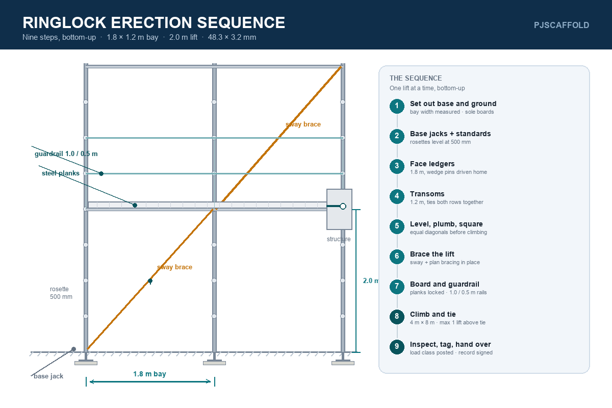
Ringlock goes up in one direction only: from the base jack to the top, one lift at a time, with bracing and ties following the frame instead of chasing it. The nine steps below are that order — set out the base, place jacks and standards, fit ledgers, fit transoms, level and plumb, brace the first lift, board the working lift, climb and tie, inspect and tag.
Get the order right and a two-person team builds a facade without rework. Get it wrong — planks before braces, three lifts before the first tie — and you are loading a frame with geometry it was never tested for. The grid itself is covered in our ringlock dimension and size chart; this guide is about sequence.
What Goes Into One Bay-Lift
Before the sequence, the building block it repeats. A standard export bay is 1.8 × 1.2 m with a 2.0 m lift, on 48.3 × 3.2 mm Q355B tube:
| Component | Size | Per bay, per lift | Unit weight |
|---|---|---|---|
| Standards (verticals) | 2.0 m | 2 | 9.7 kg |
| Face ledgers | 1.8 m | 2 | 7.3 kg |
| Transoms | 1.2 m | 2 | 5.1 kg |
| Steel planks | 1.8 m × 0.61 m | 2 | 11 kg |
| Diagonal brace (amortised) | 1.8 × 2.0 m | 0.5 | 8.5 kg |
| Approximate steel per bay-lift | ≈ 70 kg |
That single figure scales straight to an order. A 50 m × 20 m facade is 28 bays × 10 lifts = 280 bay-lifts × 70 kg ≈ 19.6 t, which is where the working rule 1,000 m² ≈ 20 t ≈ one 40ft container comes from. The full component take-off is in our ringlock component list and BOM.
The Nine-Step Erection Sequence
Step 1 — Set out the base line and check the ground
Mark the facade line and the two row lines at the actual bay width, then look at what the base jacks will stand on. Paved slab, compacted hardcore and sand all behave differently under the same leg load, and the answer is sole boards sized to the load, not wider jacks. If the ground is the weak link, everything above it inherits the problem — our ground bearing pressure guide has the numbers.
Wrong at this step: setting out to a nominal 1.8 m when the structure has pilasters or a plinth that force a 1.65 m first bay. Measure the elevation, then set out.
Step 2 — Place the base jacks and the first standards
Set each base jack on its sole board, then drop the first standard into it. Rosettes are at 500 mm centres, so line the lowest rosette of every standard up at the same height — if one standard enters its jack further than its neighbour, every ledger on that lift sits out of level.
Wrong at this step: winding the jack out to its full 600 mm stroke because the ground falls away. Keep the screw well inside its limit (a common rule is no more than two-thirds of the stroke, with at least 100 mm engaged) and step the base with sole boards instead.
Step 3 — Fit the first lift of face ledgers
Ledgers go into the rosette cups with the wedge pin driven home — hook over the ledger end, flat face down, tapped until the wedge bites. Two ledgers per bay at this stage: inner face and outer face.
Wrong at this step: pins dropped in but not driven. An undriven wedge looks connected and carries nothing, and it will not survive the first lift of climbing.
Step 4 — Fit the transoms
The 1.2 m transoms tie the two rows together and turn two parallel lines of standards into a frame. They sit in the same rosette as the ledgers, so one rosette takes up to eight connections at adjustable angles — which is exactly why a ringlock node can take a transom, a ledger and a brace at once.
Wrong at this step: transoms only in the bays where planks will go. Unbraced laterally, the frame racks as soon as anyone climbs it.
Step 5 — Level and plumb before you climb
This is the step that gets skipped when the crew is in a hurry, and the one that decides whether the next 20 m goes up straight. Check the standards for plumb in both directions, check the ledgers for level, and check the first bay for square by measuring the diagonals — if the two diagonals differ, the bay is a parallelogram and every lift above it repeats the error.
Wrong at this step: levelling with the jacks after the second lift is on. You cannot correct a leaning tower from the middle.
Step 6 — Brace the first lift
Diagonal braces go on the facade line in a zig-zag pattern, plus plan bracing in the base lift so the frame cannot rack in the horizontal plane. How often? Typical practice is a sway brace every four bays and plan bracing in the base lift and every fourth lift, but the pattern that counts is the one in the erection manual for your system — it is part of the test evidence behind the load chart.
Wrong at this step: boarding the lift first and "adding braces later". The braces are what make the frame stable while it is being boarded.
Step 7 — Board the working lift
Planks go on the transoms, locked down, butted, with no gaps wider than the standard allows. Then the guardrail set: a top rail at 1.0 m, an intermediate rail at 0.5 m, and toe boards at the platform edge. A working lift without a full guardrail set is an incomplete lift, not a finished one.
Wrong at this step: planks laid loose so they can be "moved along as we go". Loose planks slide, and a sliding plank is how people fall through a deck that looks complete.
Step 8 — Climb, and tie as you climb
From here the sequence repeats: standards, ledgers, transoms, braces, planks, guardrail — one lift at a time. Two rules run alongside it. First, ties to the structure go in as the scaffold rises, typically every 4 m vertically and 8 m horizontally, and the scaffold never runs more than one lift above its highest tie. Second, brace pattern repeats with height: the frame is only as stiff as its least braced lift.
Wrong at this step: building four lifts and tying afterwards. Between those two events the scaffold is a free-standing tower in wind, which is a different and much weaker structure.
Step 9 — Inspect, tag and hand over
Before anyone loads it: check every wedge pin, every tie, the brace pattern, the guardrails and the toe boards, then sign the handover and post the platform load class. EN 12811 classes run from 0.75 kN/m² (Class 1) to 6.0 kN/m² (Class 6); facade work is usually Class 3 at 2.0 kN/m². Whatever the class, it is a limit that the people on the platform need to be able to read.
Wrong at this step: handing over on a verbal "it's done". An untagged scaffold cannot be inspected, and an uninspected scaffold cannot be defended after an incident.
Erection Checklist
| Stage | Check | Why it matters |
|---|---|---|
| Before | Base line and bay width measured against the actual elevation | Pilasters and plinths break nominal grids |
| Before | Ground bearing verified, sole boards sized | Leg load has to reach the ground through something |
| Before | Components inspected: no bent standards, no cracked rosettes, no missing wedges | A chart is only valid for undamaged components |
| Before | Exclusion zone below, harness anchor points agreed | Nobody works under a lift being built |
| During | Wedge pins driven, not just inserted | Undriven pins carry nothing |
| During | Standards plumb, ledgers level, diagonals equal | Error at the base is repeated at every lift |
| During | Brace pattern matches the manual | Braces are part of the tested system |
| During | Ties at every 4 m × 8 m, max one lift above the last tie | Wind acts on the whole frame, not one lift |
| After | Guardrail 1.0 m / 0.5 m, toe boards fitted, planks locked | The deck is where people are |
| After | Handover signed, load class posted, inspection interval set | An inspection record is the only proof |
Where Installations Go Wrong
| Error | What it does | Fix |
|---|---|---|
| Mixing module series | Metric 0.3 m modules and the legacy 0.73 / 1.09 / 1.57 / 2.07 m series do not interlock into the same frame | One series per structure |
| Jacks over-extended | Turns the base into a hinge and puts the load on the thread | Step the base with sole boards, keep the screw inside its limit |
| Braces "borrowed" from another elevation | Leaves a lift outside the tested pattern | Brace each elevation as designed, in sequence |
| Planks not locked | Deck looks complete, slides underfoot | Lock every plank, every lift |
| Loading before handover | Material arrives on an uninspected platform | Handover first, then load to the posted class |
| Mixed suppliers' components | Rosette spacing and wedge geometry differ between systems | Keep one system and its load table together |
Two things are outside the sequence but decide whether it holds: wind, which drives tie and brace demand rather than leg load, and the load class actually applied on site. A scaffold built perfectly to Class 3 and then loaded like Class 5 has failed at the last step, not the first. The relationship between geometry, height and allowable load is in our load chart guide.
What to Ask For With the Scaffold
A ringlock package that arrives without documentation is a pile of steel. When you buy, ask for four things alongside the tonnage: the erection manual for the exact system, the load table issued for it, the EN 12810 / EN 12811 test evidence, and the component list with weights so your take-off matches what ships.
Our ringlock system is supplied hot-dip galvanized inside and out to EN ISO 1461 — mean coating ≥ 70 μm on 3.2 mm tube, local minimum ≥ 55 μm — with standards, ledgers, transoms, braces, jacks and planks from one production batch, so the manual and the load table match the steel in the container.
Send us the facade elevation and the intended platform class, and we will return the bay grid, the bay-lift count, the tonnage and the erection sequence for that layout together — request a scheme →.
Frequently Asked Questions
What is the correct erection sequence for ringlock scaffolding?
Nine steps, always bottom-up: set out the base, place base jacks and the first standards, fit the face ledgers, fit the transoms, level and plumb, brace the first lift, board the working lift, then repeat standards–ledgers–transoms–braces as you climb while tying to the structure, and finally inspect and tag. Braces go on before planks, never after.
How long does it take to install ringlock scaffolding?
Time is set by the number of bay-lifts, not by the brand. A 50 m × 20 m facade at a 1.8 m bay and 2.0 m lift is 28 bays × 10 lifts = 280 bay-lifts, each about 70 kg of steel. Two experienced operatives complete one bay-lift, boarded and guardrailed, in a matter of minutes once the rhythm is set — the total is roughly 280 × that figure plus ties and inspections.
Does ringlock scaffolding have to be tied to the building?
Yes, for any facade scaffold above a low free-standing height. Typical practice is a tie at every 4 m of height and every 8 m along the facade, with no more than one lift erected above the highest tie. The exact pattern belongs to the system's erection manual and the engineer's design.
Can ringlock be erected without the diagonal braces?
No. The braces are part of the tested system: the allowable loads in the load chart assume the tested brace pattern is installed. Removing a brace to make access easier takes the scaffold outside its test evidence.
Can I mix ringlock components from different suppliers?
No. Rosette spacing, wedge geometry and tube wall thickness vary between systems, and mixing them voids the tested capacity. Keep one system, one batch, and ask for the erection manual and load table that belong to it.