Three numbers define a scaffold before a single component is ordered: bay length (how far apart the standards stand along the facade), bay width (how far apart the two rows stand) and lift height (how far apart the working platforms sit). Choose the wrong grid and you either buy 25% more steel than you need or find that the platform you designed cannot take the load.
If you need a starting point: 1.8 m × 1.2 m bays with 2.0 m lifts. It is the export bestseller, it is what the market quotes against, and it is the grid every worked example in our guides is built on. This article explains what those three numbers control, what changing them costs, and which constraints you cannot design your way around.
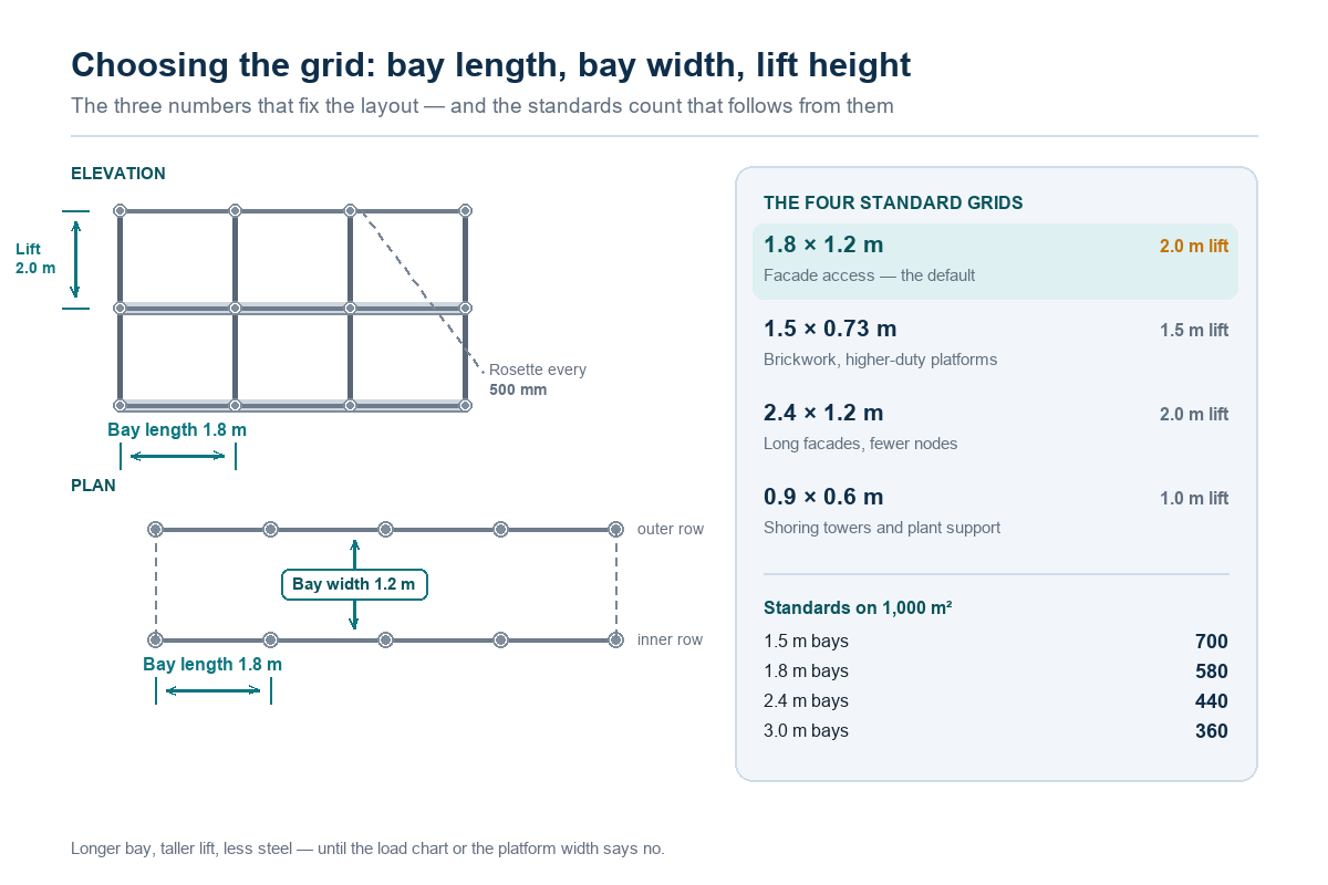
What the Three Terms Actually Mean
- Bay length — the horizontal distance between adjacent standards along the face. Set by the ledger length you choose, from the 0.3 m modulus series.
- Bay width — the distance between the inner and outer rows of standards. This is the width of the working platform, so it is driven by what has to happen on it, not by structural preference.
- Lift height — the vertical distance between platforms. Set by rosette positions, which sit every 500 mm on a standard ringlock standard.
- Standard spacing — in practice, a summary of the first two: standards at the bay length longitudinally and the bay width transversely.
All available lengths, including the full ledger series and standard increments, are in the ringlock dimensions and size chart.
The Standard Grids
Four combinations cover almost everything. Everything outside them is a bespoke design.
| Bay (L × W) | Lift | Where it belongs |
|---|---|---|
| 1.8 × 1.2 m | 2.0 m | Facade access — the default and the export bestseller |
| 1.5 × 0.73 m | 1.5 m | Brickwork, render and higher-duty platforms |
| 2.4 × 1.2 m | 2.0 m | Long, unbroken facades; fewer nodes per m² |
| 0.9 × 0.6 m | 1.0 m | Shoring towers and plant support |
The 0.73 m and 1.2 m widths are not arbitrary: they match the 0.61 m and 1.07 m steel plank modules used across Gulf and European sites, so the platform closes out without cutting boards. Our steel plank range is supplied to those same modules.
What the Grid Costs You in Steel
Bay length is above all a standards-count decision. On the same 1,000 m² facade (50 m × 20 m, double row, 2.0 m lifts), widening the bay removes lines of vertical steel:
| Bay length | Bays along 50 m | Standards required | Ledger tonnage | Effect |
|---|---|---|---|---|
| 1.5 m | 34 | 700 | ≈ 4.2 t | Most steel, highest permissible load |
| 1.8 m | 28 | 580 | ≈ 4.1 t | The export standard |
| 2.4 m | 21 | 440 | ≈ 4.0 t | 24% fewer standards |
| 3.0 m | 17 | 360 | n/a — bespoke | Needs longer ledger sections and a re-checked design |
The ledger tonnage is almost flat across those columns — longer ledgers weigh more each, and there are proportionally fewer of them. Standards, not ledgers, are where bay length shows up on the invoice.
Lift height works the same way on the vertical axis:
| Lift height | Lifts to 20 m | Standards required | Consequence |
|---|---|---|---|
| 1.5 m | 14 | 812 | More platforms, shorter climb between them |
| 2.0 m | 10 | 580 | The convention for facade access |
| 2.5 m | 8 | 464 | Fewer platforms, longer reach between lifts |
So the cheapest possible frame is a wide bay with a tall lift. It is also, usually, the wrong choice — for the reasons below.
What the Grid Changes Beyond Cost
- Permissible load. A longer bay puts more load on each node and each ledger. The permissible load is read off the system's load chart for that specific grid, not assumed — which is why our load calculation guide treats the grid as an input to the design rather than a commercial preference.
- Number of nodes to pin. A 1.5 m grid needs 700 standards on a 1,000 m² facade; a 2.4 m grid needs 440. Every one of those is a set of wedge connections to drive. On a large facade the labour difference is measured in shifts.
- Platform width. A 0.73 m wide bay is a working platform for one trade. Add materials and you need 1.2 m — and a 1.2 m bay is 64% more transverse ledger than a 0.73 m one.
- Climb and access. Taller lifts mean fewer platforms but longer climbs; on anything above two lifts you are into ladder or stair tower access, which is a component list decision of its own.
The Constraints You Cannot Design Around
| Constraint | Effect on the grid |
|---|---|
| Plank modules | The platform must close out in 0.61 m or 1.07 m plank widths — bay widths of 0.73 m and 1.2 m exist for that reason |
| Standard increments | Standards come in 0.5 m steps, and rosettes sit every 500 mm, so lifts are set in 0.5 m increments |
| Dimensional series | The metric 0.3 m modulus and the older European series (0.73 / 1.09 / 1.57 / 2.07 m) cannot be mixed in one structure |
| Working height / base ratio | Slender, unbraced elevations need more ties and bracing; a tall narrow scaffold is a design problem, not a bay-length problem |
| Tie frequency | Ties are set by the wind design. Expect intervals of roughly 4 m in both directions on medium-height facades — more where the scaffold is netted or exposed |
| Ground and foundations | Leg load rises as bays narrow; the base jack and the ground under it must be checked, not assumed |
Choosing for Your Market
- Gulf projects (UAE, Saudi Arabia): the 1.8 × 1.2 m / 2.0 m grid dominates facade work. Our UAE and Saudi Arabia pages summarise local practice.
- Europe: identical dimensions, but approvals lean on EN 12810 / EN 12811 system testing rather than national conventions.
- Heavy shoring: shorten bays to 0.9–1.2 m and specify 250 mm rosette spacing. Narrow bays and dense rosettes are the correct answer when the load, not the access, defines the job.
The One-Line Summary
Longer bay, taller lift, less steel — until the load chart or the platform width says no. Fix the grid with three questions: what has to happen on the platform, what load class does the client require, and what does the load chart allow at that spacing. Everything else in the take-off follows automatically.
Send us your facade dimensions and the load class you are designing to. We will return a take-off in the grid you have chosen, plus the load chart data for it, and flag it if a different grid would serve you better. Send your project parameters →
If you are starting from the facade area rather than the grid, run the take-off formula first — it turns the area into component counts, and the grid then adjusts the totals as shown above.
Frequently Asked Questions
What is the standard bay length for ringlock scaffolding?
For facade access the standard export bay is 1.8 m × 1.2 m with a 2.0 m lift. Ringlock ledgers follow a 0.3 m modulus, so bay lengths are chosen from 0.9, 1.2, 1.5, 1.8 and 2.4 m.
What is a scaffold lift height?
The vertical distance between one working platform and the next. 2.0 m is the convention for facade access and matches four rosette positions on a 500 mm spacing; 1.5 m lifts are used for brickwork and higher-duty platforms.
What is standard spacing for scaffolding standards?
Standards sit at the bay length along the facade and at the bay width across it — typically 1.8 m and 1.2 m. Spacing is a design decision, not a fixed value: it sets the load each standard carries.
Does a longer bay mean less scaffolding?
Yes for the frame. Moving from 1.8 m to 2.4 m bays cuts standards from about 580 to 440 on a 1,000 m² facade — roughly 24% off the heaviest line. Ledger tonnage barely changes, but permissible load must be re-checked against the load chart.
Can I mix 2.4 m bays with 1.8 m bays on one scaffold?
Yes, provided the engineer designs the transition and the components come from the same dimensional series. Do not mix the metric 0.3 m modulus with the older European series (0.73 / 1.09 / 1.57 / 2.07 m) in one structure.